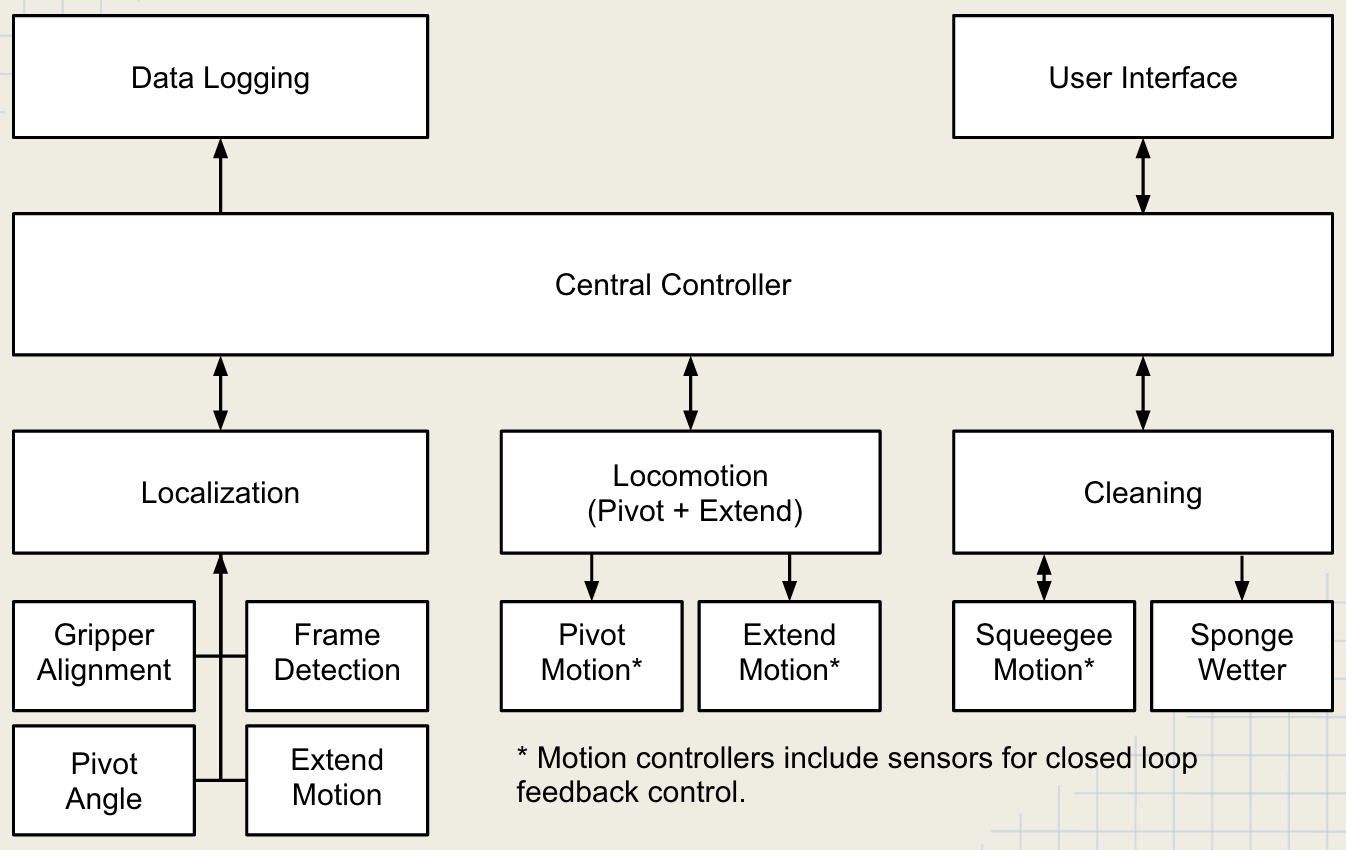
Functional Architecture
The functional diagram illustrates on a high level how data is gathered and passed through the system. As the robot cycles between states of moving and cleaning, the sensors provide feedback. This information, once relayed to the controller can dictate the motion of the mechanisms.
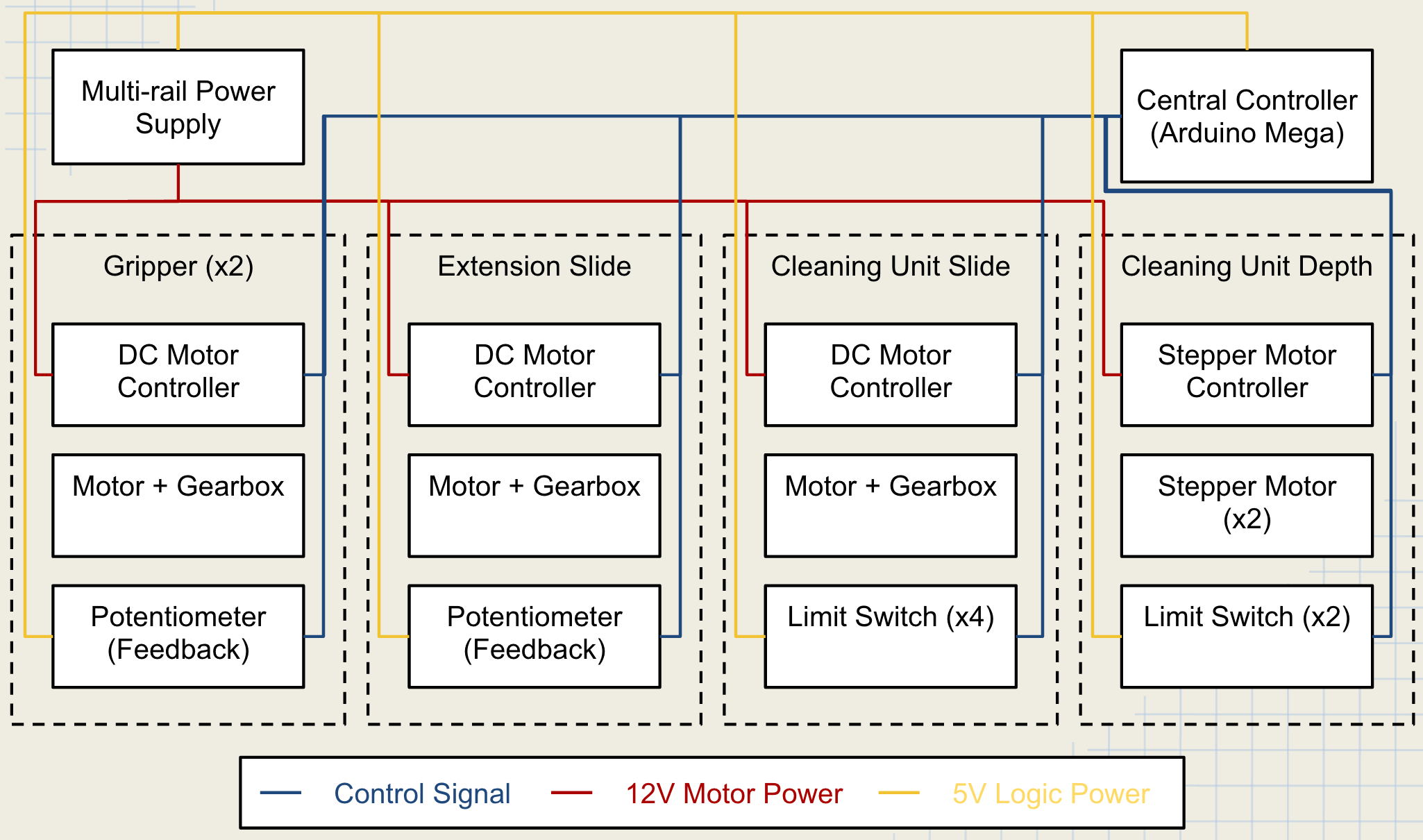
Cyberphysical Architecture
Control
We will be using an asynchronous parallel control system with 4 threads (localization,window path planning, safety, logging). We will be using a real time OS to allow for all four threads to run simultaneously.
Localization
The localization thread will manage the robot understanding of its location. When a new sensor event occurs a callback will fire. Causing for the internal representation of the robots internal understanding of its state to change. Each sensor input will be filtered over time using a kalman filter, giving us an evolving state estimate and confidence of each state variable. The state will be available to all of the other threads.
Window Path Planning
To minimize the travel time of our robot and to minimize the amount of resources (power/cleaning fluid) that the robot uses we will pre plan a path on the building. This can be split into a macro and micro problem.
Macro Problem
Create a graph of all window area’s to be cleaned. The nodes will be the window sections that need to be cleaned. The edges will be the cost of moving between each set of adjacent window areas. An MST (minimum spanning tree) will then be created from the graph. The Robot will then follow the MST by executing a depth first search. Each window will have four nodes on it one on the top left, one on the top right, one on the bottom left, one on the bottom right. The cost of moving between each of the four corners will be very low compared to the cost of moving between the window panes. The four corners are needed incase windows of different size exist on a window panel.
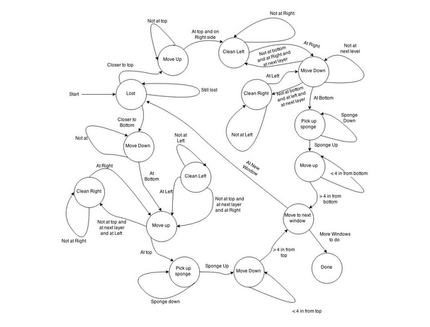
Micro Problem
Move to the top or bottom of the window, snake away from the horizontal edge that the robot is currently at. While the robot is moving along the window it will be verifying that the window is cleaned.
Logging System
The system logger will record the state of the system. This information will be written to disk locally and broadcast over a radio serial link so that a monitoring computer can view the current state of the robot.
Safety System
We will have two error states. Immediate stop: Shut down right away, this is what will happen when an emergency stop button (physical or virtual) is pressed or a critical error is encountered. This error state will be used sparingly as it causes for the robot to stop all operations. This can be dangerous if the robot were to be in the middle of a movement. System Error: Shutdown when statically stable: this error state is designed for when the robot encounters an error which stops it from being able to continue its job but does not impose any potential for harm to the robot or people around the robot.
A thread will be running which continually checks the following assertions, if any of the following statements are ever false then an error state will be entered into until the robot is reset by an operator.
- physical emergency stop pressed
- emergency stop signal sent via wireless serial link from monitoring laptop
- battery power extremely low
- position estimate is outside of bounds