System Performance
Mechanical
Frame Gripper
A quick test was run to figure out how much weight our current gripper prototype could support. A clamp was attached to the gripper and a bag was hung off of the clamp at the distance that we expect the center of mass of the robot to be away from the window. Weight was added to the bag until failure, which occured at around 5 lbs. Currently, we are leaning towards using the weight of the robot to hold onto the frame. The proposed way to accomplish this is by clasping on with a C-clamp and allowing for the top and bottom of the clamp to apply normal forces to the frame.
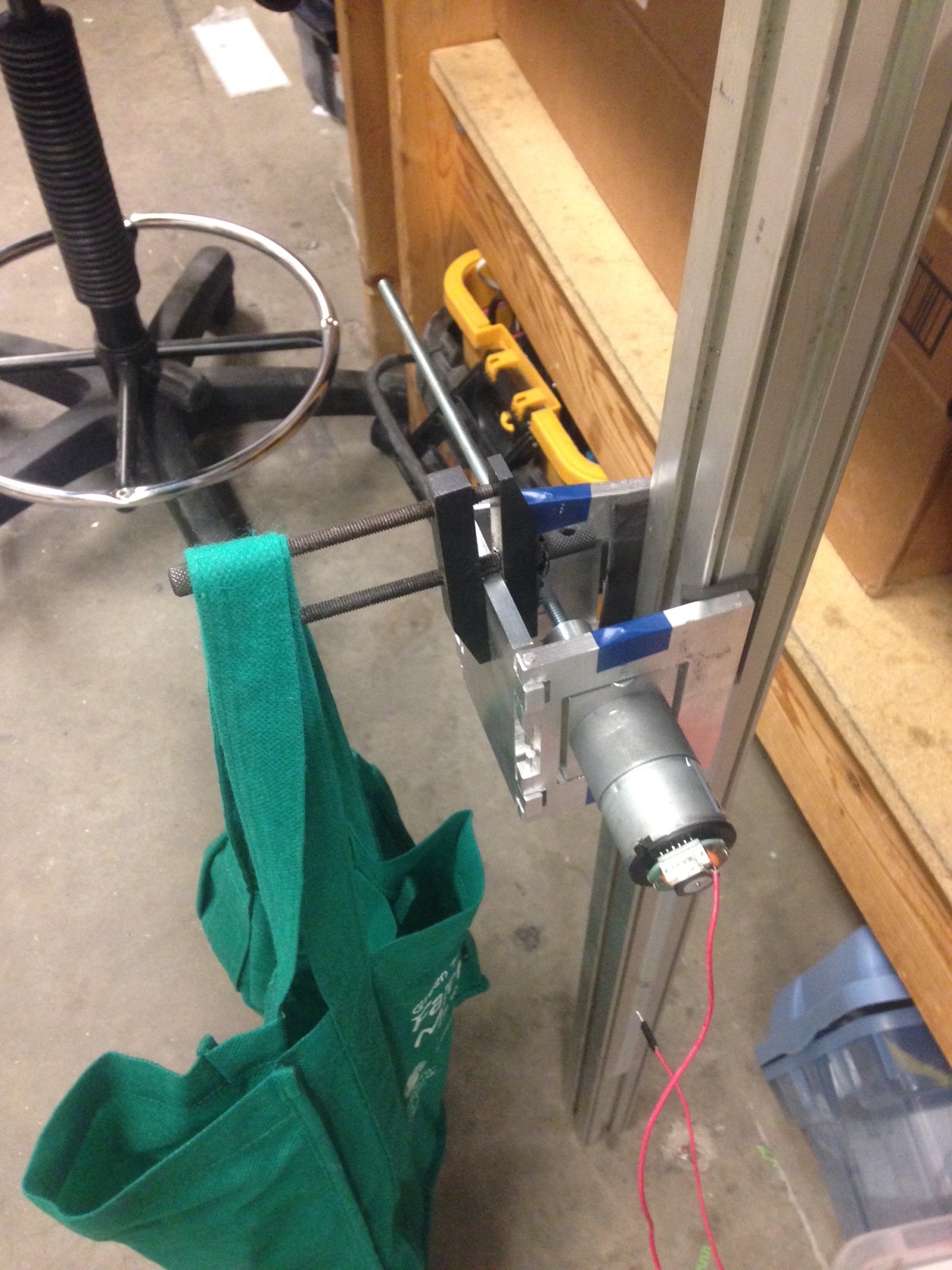
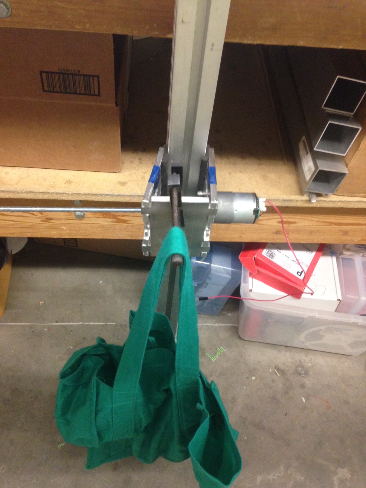
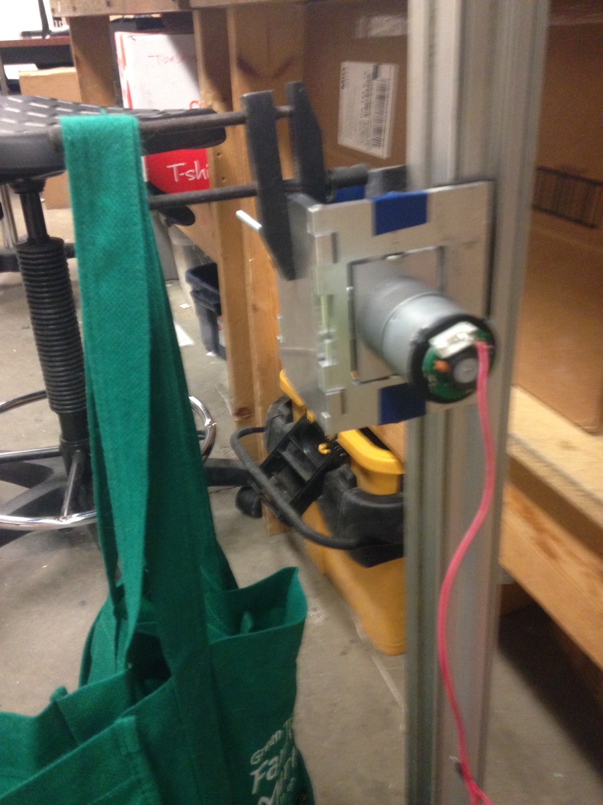
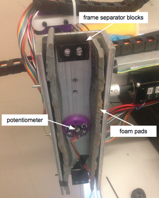
The final iteration, however, consisted of two large pieces of aluminum c-channel with rubber padding. The c-channel fits over the frame of the window, and when the full weight of the robot is applied to the gripper, the large resulting moment creates a friction lock as the top and bottom of the c-channel bind against the window frame. The rubber padding increases the coefficient of friction to prevent slipping. One large advantage to this mechanism is that the weight of the robot actually helps the grippers stick to the window frame by applying more normal force and thus creating more friction.
Extending Arm
The extension arm has been built and has been tested. The lead screw is able to power the extending arm quickly as long as there is enough current from the power supply. Due to the length of the lead screw, we are concerned about the binding of the lead screw. There are also some concerns regarding the weight of the arm but due to the transfer gearbox but we will attempt to cut down on the weight in a way that would not compromise function.
Cleaning Unit
The cleaning unit is currently being built and undergoing testing. We have been testing the fit of various components on the cleaning unit and soon the whole cleaning unit can be printed and tested. One cleaning unit for the extending arm was printed and we successfully got it to slide smoothly on the extension arm. Since the power chain needs to be wound up on both ends, we will need to design a housing to keep the chain compact.
Pivoting Unit
The pivoting motion is dictated by a gearbox with a worm gear. It has been assembled and is in the process of being tested. From testing the pivoting unit, we understood the importance of material selection and failure modes. At first, we made the spacers out of acrylic which yielded under the stress of the turning gear. The next step is to make new spacers of a larger radius out of delrin or alumnium to withstand the stresses. This improvement will allow us to continue testing.
Replacing the spacers with harder metal ones was sucessful. The Pivots are functional as designed.
Control System
We currently have working firmware that controls the screen on our development board. To use this, we had to bring up the SPI and GPIO interfaces, and the program uses the system timers to generate data for the screen. We also wrote our own makefile to build the hardware support libraries and our own code. We have been able to connect an external debugger to understand issues with the firmware, which will be very powerful for future development. Our next steps are to write a motor control module.
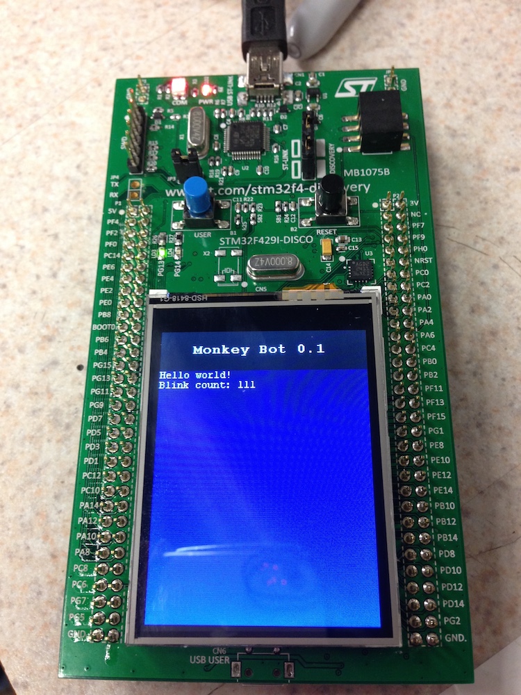
Our "Hello World" program running with screen support.
Unfortunately, we were not able to fully bring the ST Discovery board up to the operational level that was needed for our robot so we had to move our project to Arduino C++ code in the week before final demos. We were able to have the st discovery board produce pwm signals, digital signals, and read both analog and digital signals. However when we tried to have the board read analog signals using its built in adc we were unable to consistently produce valid pwm signals. It is believed that this error was caused by the use of a single pin for both functionalities but we ran out of time to fully debug the issue.
While rushed, the move to Arduino was successful, we were able to avoid the problems which were discussed previously by reimplementing all arduino function ourselves so we knew exactly which pins and timers were in use at any time. The Arduino based control system handled the same number of inputs and outputs for motors and sensors. However, it lacked the user interface and feedback through a touch screen. This was not a core feature of our embedded software, so the tradeoff was worth it.
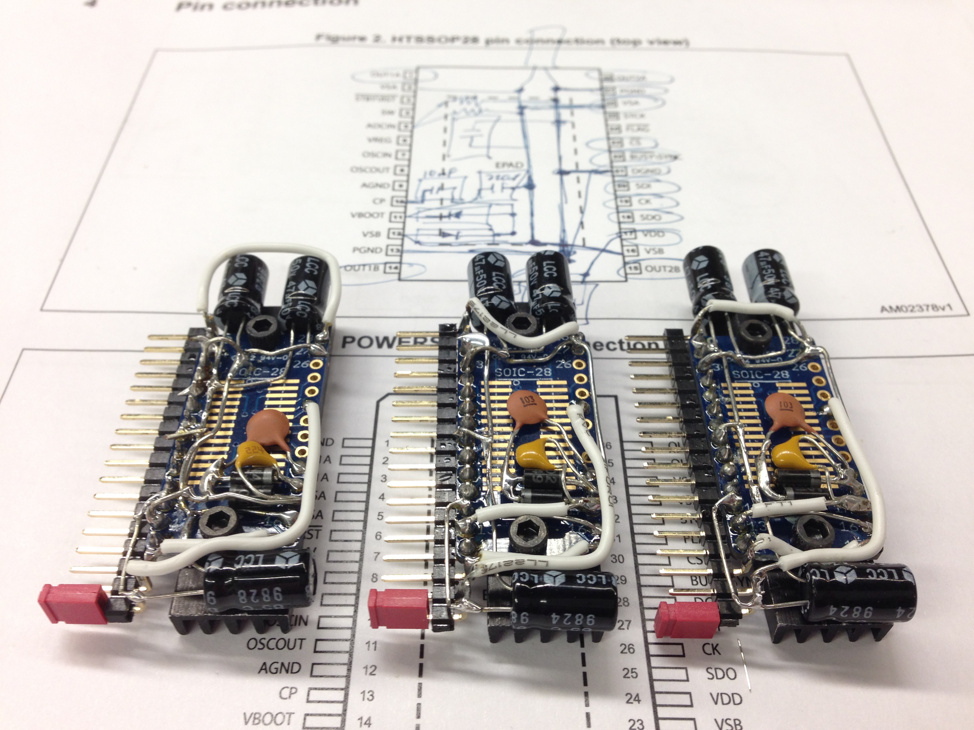
One feature that was not implemented with the final system is our stepper motor controllers. We electrically/physically built them and tested them using a test controller. They moved our steppers accurately with minimal control. These drivers have internal counters and clocks to manage moving at a given speed or to a given position. The ST L6470 was mounted on a SMD breakout board and the external circuitry required was soldered to the breakout. A heatsink adds current capacity to the system. Hopefully, we will be able to use these in a future project.