System Implementation
Mechanical
Frame Gripper
A gripper is used to hold the robot to the window frame made of 80/20 aluminum. The gripper needs to be able to support the whole weight of the robot and as a result, it needs to be long to cover enough surface area. The gripper currently has two plates, connected with a lead screw. With a motor, the lead screw drives the plates together to secure the robot onto the frame.
Extending Arm
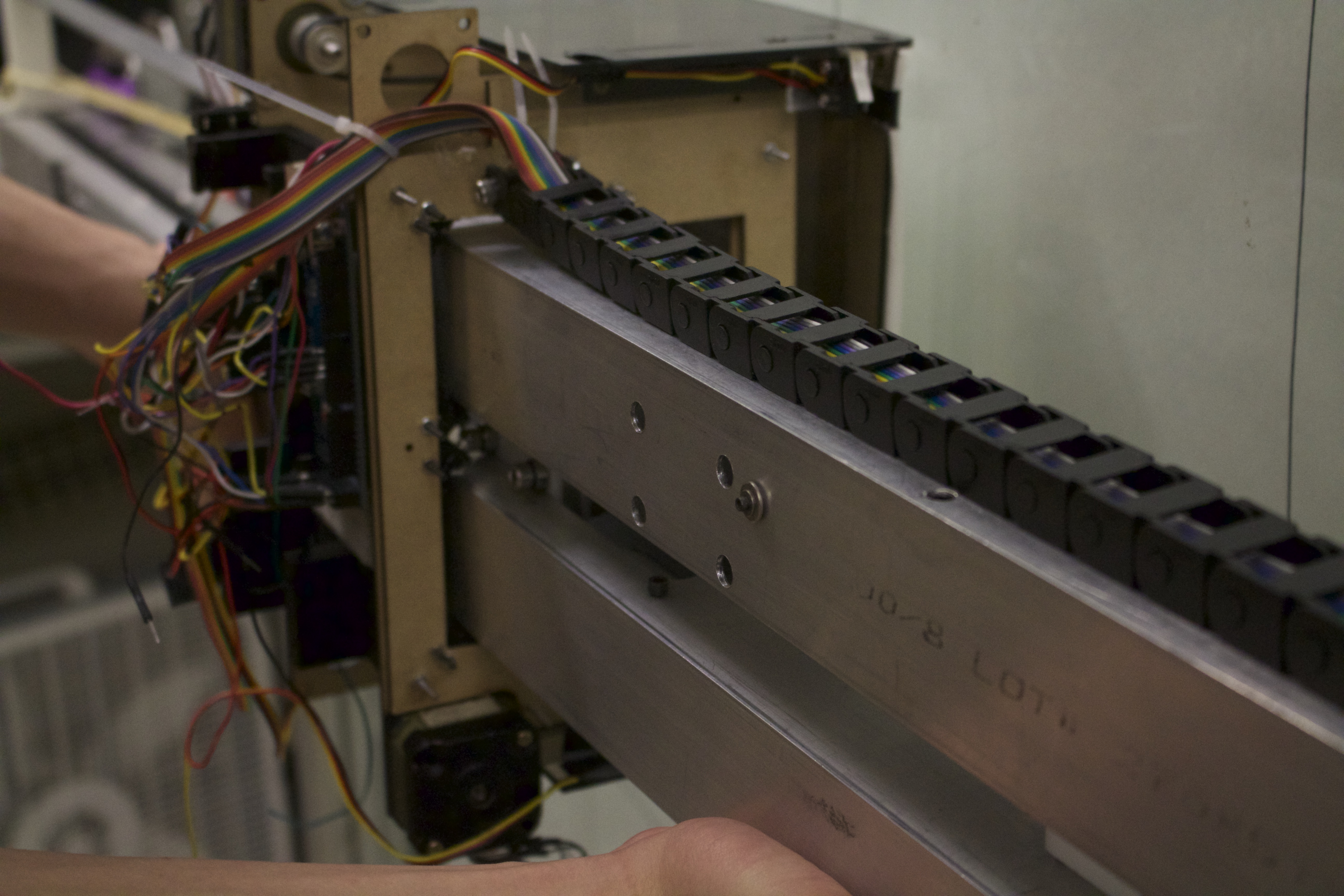
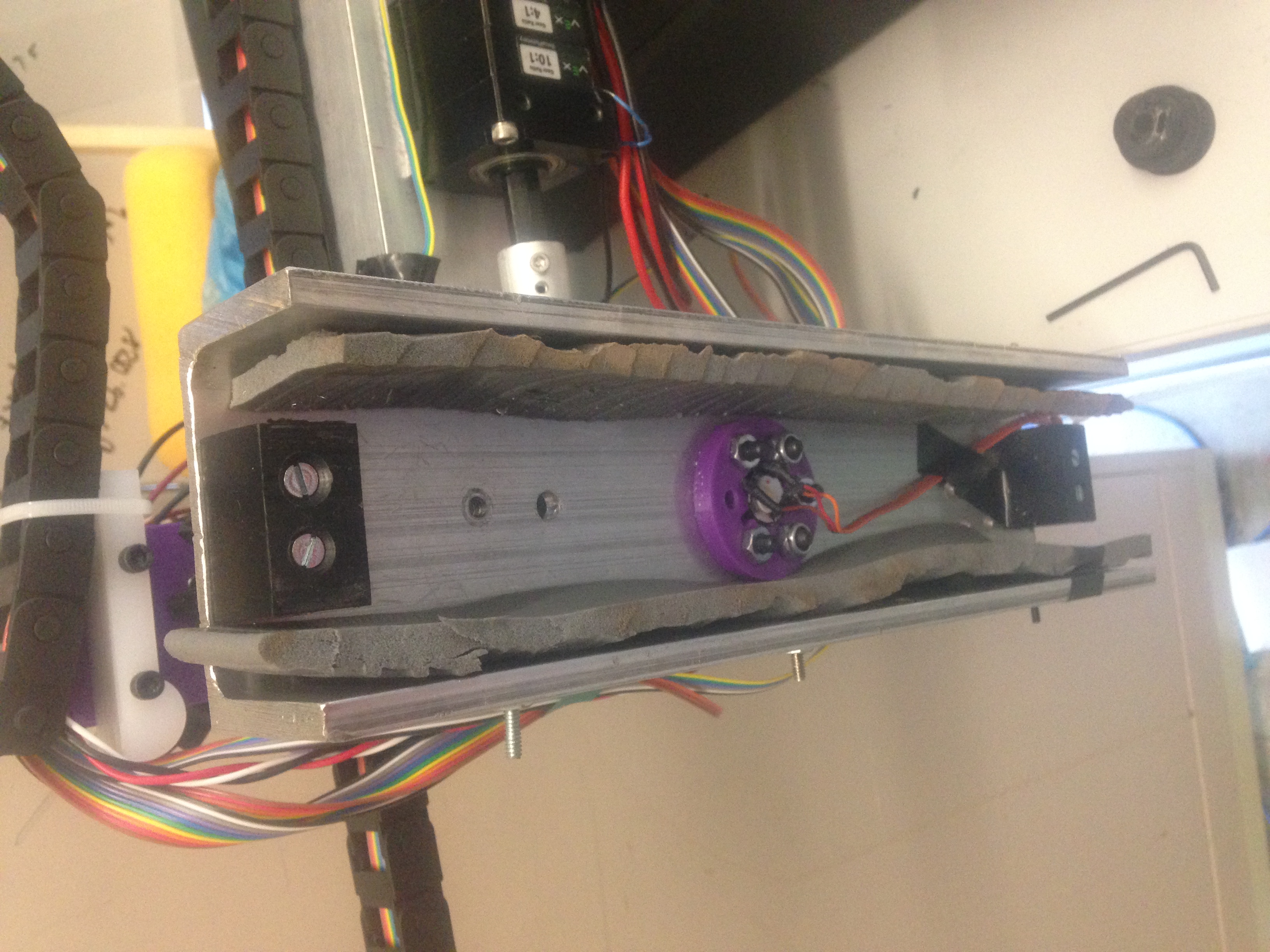
A core feature of our design requires moving a cleaning unit horizontally on the window. We have built an extending unit that the cleaning unit can move on. To adjust for different size windows, two blocks with bearings allow the extending arms to slide past each other adjust between the 3 and 5 foot bounds of window size. This slide is powered by an ACME lead screw attached to a motor. The motor and the end of the lead screw are mounted to plates inside the extending arm. Limit switches can be used to zero position after the arm has changed length. The arm will be made of 2in x 2in, thin-walled aluminum to help maintain stiffness.
Cleaning Unit
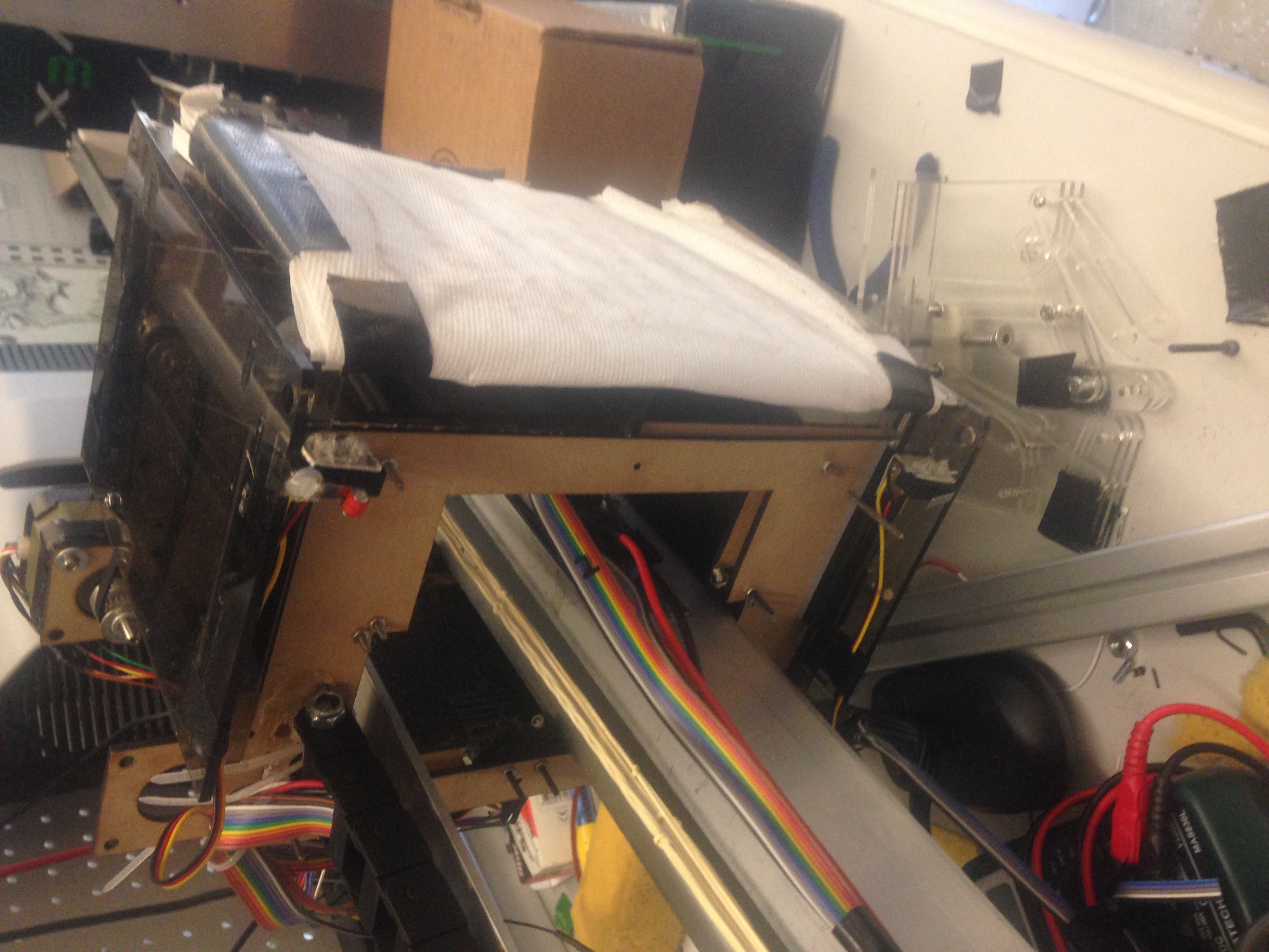
The actual cleaning unit that will translate from side to side on the telescoping arm comprises of a large sponge and two separate squeegee edges. The sponge is in contact with the glass surface and the unit will move across the window in order to clean it. There is a water tank on the back side of the sponge to allow for a little bit of water to be deposited for dried debris. There are also squeegees on both sides of the cleaner for the purpose of pushing any excess liquid along the window. The squeegees are able to move towards and away from the window via four small servos. The unit will be guided along the telescoping arm using a power chain.
Pivoting Unit
The pivoting joint allows movement in the plane parallel to the window. This allows us to move the whole extension arm horizontally and diagnolly to climb up and down the window. This movement will be realized through the implimentation of a planetary gearbox with a shaft and worm gear that will allow us to pivot both units at the same time with one motor.
Software
We orginaly chose to build up our control system on a STM32 F4 Discovery board. This prototype board has a 32-bit ARM Cortex M4 processor, lots of on-chip IO (UARTs, SPI, I2C, PWM in and out, GPIO), and a built in screen. This board can be programmed using the ARM GCC Embedded toolchain and debugged in hardware with GDB. ST provides example source code, although they do not officially support GCC or provide makefiles. Towards the end of the project we switched to useing an arduino mega.