System Design
To meet the performance specifications, we are designing a mechatronic device that incorporates a microcontroller for system control and mechanisms to grip, pivot and extend to move along the window frame.
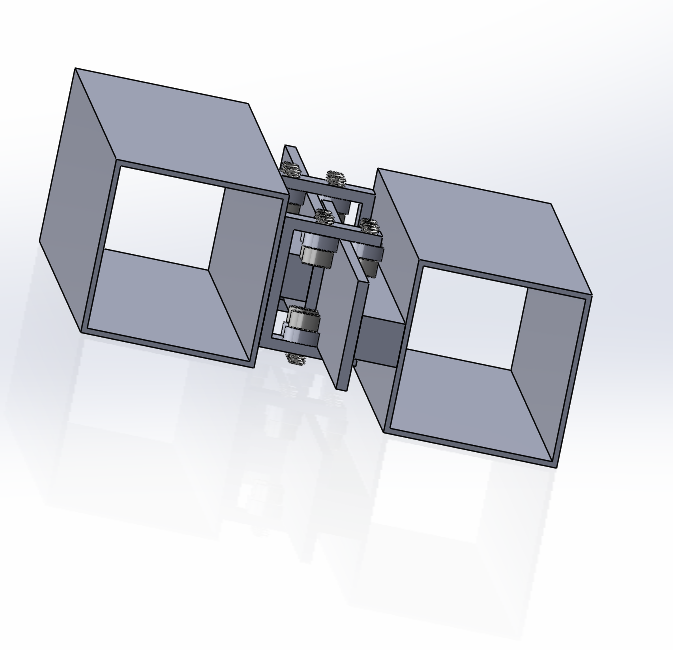
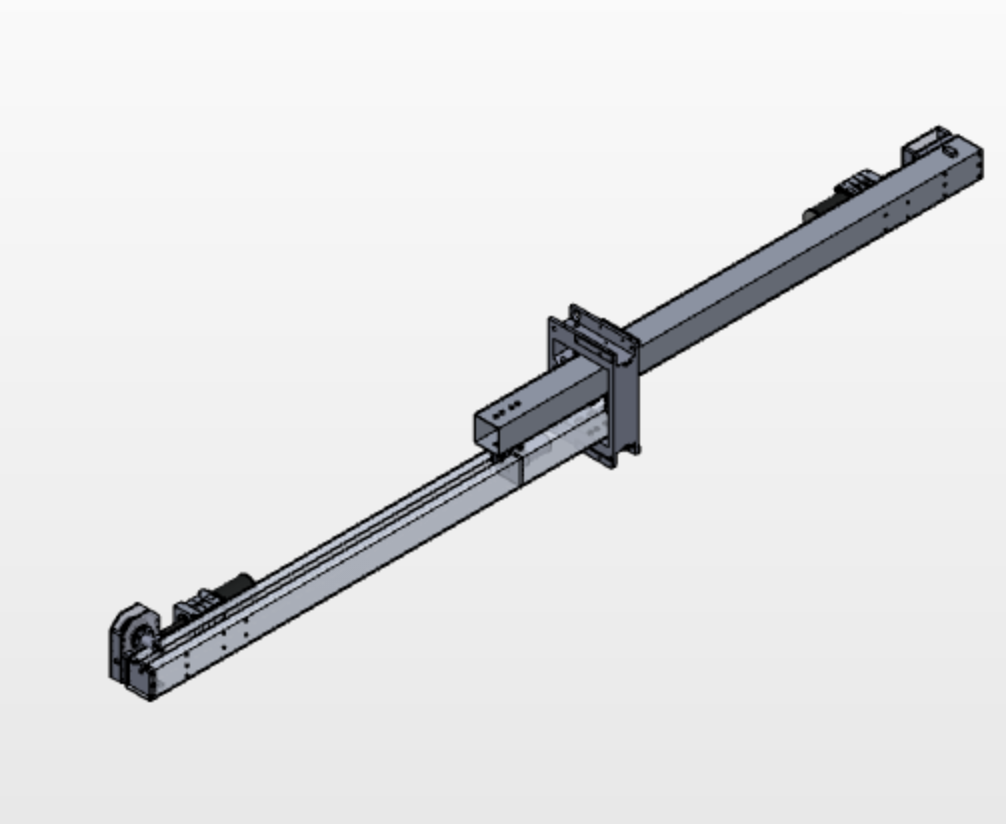
The robot is comprised of three separate units: a gripping unit, an extending unit and a washing unit. The gripping unit is placed on the two ends of the robot to hold the robot onto the sides of the window frame. Since there is a short distance between the top of the frame and the window, these grippers cover a large surface area parallel to the window to apply more pressure. This also more effectively counters moments due to the weight of the robot. A motor with a planetary gearbox is attached to the gripper to create a pivoting motion about the gripper. The extending unit consists of two offset beams attached together with bearings mounted to a block to form a linear slide. The motion of the beams is driven by a motor and lead screw. The cleaning unit moves along the extending unit using a power chain.
At the beginning of the window washing process, the grippers are attached to both sides of the frame. As the robot shuffles up the frame, releasing the gripping and extending the arm as it climbs, the cleaning unit slides back and forth to clean a section of the window.
Design Iterations
Many design improvements have been made since the start of the project. Firstly, the T-rail has been removed due to size and manufacturing considerations. By using bearing blocks instead, we have been able to reduce the height of our robot by half. As for our gripping unit, we have been able to move from a four-bar linkage to a clamp design which has allowed us to cut down on size and, as result, reduce the distance away from the window pane. This was an essential in minimizing the torque that causes the robot to fall away from the window. The pivoting unit has seen improvements in material selection. Due to failures that occurred in testing, we are now using metal instead of plastic to transfer loads. The cleaning unit has also undergone many changes in design that have improved our motion along the extending arm as well as our contact with the window surface. Overall, due to all the modifications illustrated above, we have been able to decrease the complexity of our subsystems to create a more compact and efficient robot. Here are some of the specific design consideration we made for our subsystems.
Locomotion
Originally, we considered many methods of locomotion for the whole robot. We considered using suction to attach ourselves to the window. This would have allow us to move freely to any part of the window. The base of the Winbot 730 by Ecovacs [2] has an inner ring that is connected to a vacuum pump which holds the robot to the window. One of the disadvantages of the this method include streaking caused by the suction mechanism and loss of suction due to dirtying of the surface. Also, the area under the suction mechanism will be left uncleaned in the end. Therefore, we decided to explore other attachment options. We briefly discussed using magnets to secure the robot and clean both sides of the window. However, since having a magnetic attachment on the inside would be unrealistic in the cleaning of skyscrapers, we decided to pursue other avenues. The possibility of using a quadrotor or another type of flying mechanism as a means of locomotion was considered. This would allow for the robot to be very versatile and mobile, but in the end, issues with weight, controls, precision, and varying expected air conditions (outside of a skyscraper) also rendered this idea unfeasible.
We decided to proceed with moving up and down the window by gripping on to the frame because it was the most realistic considering the structure of skyscraper windows and our design goal of moving between window panes. To be able to move between window frames, our robot needed to be able to hold onto the frame from just one side to flip. By choosing an acceptable deflection value for our application, we could calculate the outer and inner diameter of the beam that we needed. We chose to build the body out of thin-walled extruded aluminum for strength and chose a 2 inch x 2 inch cross section because it would prevent deflection.
As for the pivoting motion, we knew that we needed a high gear ratio, to allow for lifting from just one end. At the beginning, the motion of the two pivoting gearboxes were coupled with shafts, allowing us to drive both grippers with one motor. We eventually had to use two motors due to a change in our gripper design. More details and technical justification can be found in the subsystem section.
Localization
In order to ensure that all parts of the window are being cleaned adequately, we first brainstormed ways to determine location on the window. At first, we considered using vision. This involved us attaching cameras to both sides of the robot and using the images of the frame to position the gripper correctly for climbing. More specifically, current camera images could be compared to an image with the ideal orientation of the frame relative to the gripper. This would allow for adjustment of the gripper until the two images matched. This idea was discarded because it would require that we had a camera near the center of our grippers. After the first prototype of this software was working we decided to not continue its development due to the added complexity of including it in our software stack. Our final design used the feedback mechanisms built in to each subsystem (potentiometers in the grippers, limit switches on the cleaner) to keep track of which parts of the window we have already gone over.
Cleaning
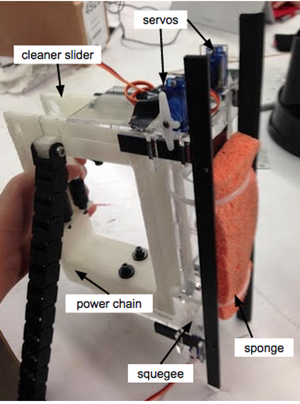
The first iteration of the cleaning unit included a squeegee and sponge pair that would be actuated back and forth. The sponge also had a gravity-fed water tank. We thought this was the optimal combination since the sponge could scrub and soak up dirt while the squeegee pushed the dirt to the bottom of the window as the cleaning unit moved. However, from brief testing with a sponge, we realized that a single sponge would get dirty quickly and thus, not clean the window effectively. To mitigate this issue, we designed a cleaning unit with a rotating component to allow for the cleaning surface to be automatically switched out once it gets dirty.
Electrical and Control Architecture
At the beginning of the semester we decided to attempt and use ST-Discovery 32F429 board as our microcontroller. This embedded computer would have allowed for us to have a Real Time Operating System (RTOS) running on the robot, making the control work much easier. Additionally it would have allowed for us to display debug information to the boards lcd. Moreover the discovery board does not have the same quarks and undocumented behavior that arduinos can show for larger more complex projects which use multiple libraries. Unfortunately, we were not able to fully bring the ST Discovery board up to the operational level that was needed for our robot so we had to move our project to Arduino C++ code in the week before final demos. We were able to have the st discovery board produce pwm signals, digital signals, and read both analog and digital signals. However when we tried to have the board read analog signals using its built in adc we were unable to consistently produce valid pwm signals. It is believed that this error was caused by the use of a single pin for both functionalities but we ran out of time to fully debug the issue.
While rushed, the move to Arduino was successful, we were able to avoid the problems which were discussed previously by reimplementing all arduino function ourselves so we knew exactly which pins and timers were in use at any time. The Arduino based control system handled the same number of inputs and outputs for motors and sensors. However, it lacked the user interface and feedback through a touch screen. This was not a core feature of our embedded software, so the tradeoff was worth it.